


Copper Electrorefining: High-Purity Copper Production with Energy-Saving & Eco-Friendly Advantages
Copper electrorefining is the world's dominant process for producing high-purity electrolytic copper. More than 80% of global copper output relies on this route, which takes cast anodes and turns them into Copper Cathodes (≥ 99.99% Cu) in polymer concrete electrolytic cells, while recovering valuable by-metals from anode impurities.
Copper electrorefining solutions balance stable production performance, operational reliability, and the demand for energy saving and emission reduction.

Electrolysis Workshop
Selling Points of Copper Electrorefining Technology
The following are the practical, cost-saving solutions that our rich field experience brings to you:
1. Sensible scheduling of cathode and anode plate removal from the cells, easing the pressure on the upstream anode furnace
2. Additional output of the by-products copper sulfate and nickel sulfate, adding extra revenue to your company
3. Energy saving and eco-friendly, reducing the consumption of electric power and steam. This saves money in the long run
4. Reliable whole production line, reducing downtime and maintenance costs
5. High-quality anode plates and cathode copper, commanding a good price whether you sell them directly or produce downstream products
6. Professional training for your staff until your plant runs efficiently and independently. A true turnkey project that saves you effort and money while making money for you

High-purity electrolytic copper production
From Anode to Cathode: How the Refinery Runs
The design scope covers the electrolytic refining and electrolyte purification (including nickel sulfate) processes:
Electrolytic refining adopts large-format permanent stainless-steel cathode electrolysis technology.
Electrolyte purification uses a "vacuum evaporation concentration - water-cooled crystallization to produce crude copper sulfate for de-coppering + electrowinning impurity removal" process, while nickel sulfate is recovered through vacuum evaporation and freeze crystallization.

Electrolytic Flow Diagram
Electrorefining Workshop
- Anode plates are transported by forklift from the storage yard to the anode preparation unit. After processing, they are lifted into the electrolytic cells by a dedicated crane at a 100 mm electrode spacing.
- Cathode cycle of 9–10 days and anode cycle of 18–20 days; after removal, cathodes are stripped, weighed and packed into the finished-product warehouse, while the stainless-steel cathode blanks are re-racked and lifted back into the cells.
- Scrap anodes are washed and sent by forklift to fire refining, or used as cathodes in the de-arsenic cells of the electrolyte purification workshop.
- Electrolyte circulates from the circulation tank through horizontal circulation pumps to plate heat exchangers, is heated to about 62–65 °C, then enters through the bottom piping and returns to the circulation tank via the overflow outlets at the top of the cell.
- To stabilize the electrolyte composition, part of the electrolyte is sent to the purification step to ensure cathode copper quality. During cell loading and unloading, the supernatant enters the storage tank and, after polishing filtration, returns to the circulation system.
- Anode slime is piped to the anode slime tank. Copper is leached and separated within the workshop for precious metal recovery, and the filtrate returns to the circulation system after polishing filtration.

Electrolytic cell surface - Anode slime settles at cell bottom during refining cycle
Electrolyte Purification
- Polluted electrolyte is pumped into the polluted electrolyte storage tank, flows by gravity from the vacuum evaporation high-level tank to the circulation pump, and is fed to the plate vacuum evaporator for continuous evaporation and concentration.
- The evaporated solution is pumped to the water-cooled crystallizer; the crystal slurry flows by gravity to the belt vacuum filter for solid-liquid separation. The separated crude copper sulfate is weighed, packaged and sold, or re-dissolved and returned to the electrolytic workshop.
- The crystallization mother liquor is heated to about 60 °C and enters the de-coppering electrowinning cells; when the copper ion concentration drops below 0.5 g/L, the power is cut and the cells are emptied.
- The supernatant from cell emptying is discharged to the final de-coppering solution tank, filtered and sent to the nickel sulfate process; black copper slag is filter-pressed, and its filtrate is sent together with the final de-coppering solution to the nickel sulfate process, while the black copper plate/powder goes to smelting or sale.
- Harmful gases such as acid mist and arsine generated during electrowinning are extracted through collection hoods above the cells, treated, and then discharged.
Nickel Sulfate Process
- The fully de-coppered solution is pumped to the de-nickeling storage tank, then to the vacuum evaporation distiller, where it is heated by steam to 80–85 °C and boiled under a 400 kPa vacuum (make-up solution is supplemented from the replenishing tank).
- After concentration to a density of about 1.6 t/m³, it flows through the overflow pipe into the water-cooled crystallizer (crystallization temperature 45 °C). The stirred and cooled crystal slurry overflows by gravity to the belt vacuum filter to separate crude nickel sulfate.
- The filtrate (recovered acid) is returned to the electrolytic workshop.
Energy-Saving Practices
Steam and electric power represent the major energy consumption points for copper electrorefining facilities. A set of practical measures can substantially improve energy efficiency.
Steam Consumption Reduction
- Cover electrolytic cell surfaces with nylon cloth to curb electrolyte evaporation heat loss.
- Apply polyurethane foam thermal insulation on electrolytic cell outer walls to reduce surface heat dissipation.
- Use high-efficiency plate heat exchangers for electrolyte heating to lift heat transfer performance.
- Recycle all condensed water to reuse residual heat sources.
- Strengthen the thermal insulation measures of the building structure to reduce the heat loss.
Power-Saving
- Regular cleaning and surface treatment help reduce electric loss.
- Adopt plate linkage line operation unit to minimize short-circuit risks and lifting current efficiency.
- Strengthen insulation on cell bottoms and edges to prevent stray current loss.
- Select high-voltage equipment with nearby substations to cut transmission loss.
- Using rectifier circulating water system to raise circulating water utilization.
- Deploy integral-cast vinyl resin electrolytic cells: current efficiency can rise by about 0.5%, saving roughly 150,000 kWh of electricity per year.
- Select low-power, energy-saving motor, saving 15 %.
- Apply High-efficiency silicon-controlled rectifier with power factor > 0.9 .
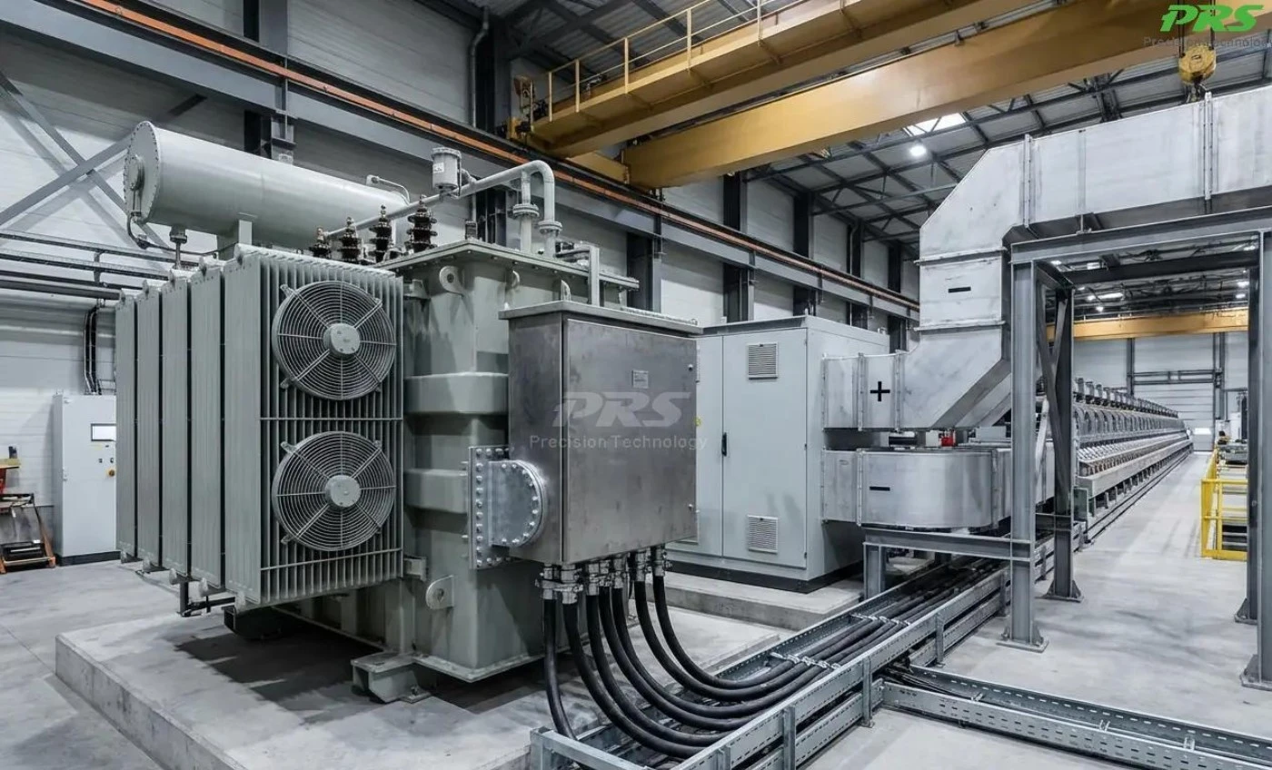
Rectifier (onsite installation)
Environmental Protection
Storage tank control waste gas, water, solid waste, and noise:
- Cell covering and negative-pressure ventilation, with FRP scrubbers reaching over 90% removal efficiency.
- Zero process wastewater discharge through full recycling.
- Qualified third-party recovery of anode mud for rare and precious metals.
- Vibration damping and silencers to meet factory-boundary noise limits.
Summary
Copper electrorefining stays irreplaceable for manufacturing high-purity copper. By combining mature process know-how with targeted energy-saving hardware and strict environmental controls, operators can achieve dual goals: stable, high-quality copper output together with a lower resource footprint and cleaner plant operation.


